Vauxhall Vivaro / Renault Trafic / Nissan Cabstar, Immobiliser fixed red light repair
Fixing the common red light, immobiliser issue with Vauxhall, Nissan & Renault vans.
The common issue of the immobiliser staying on with Vauxhall,Nissan and Renault Vans is well documented on the internet, but there isn't a single source for all items to check, to fix this yourself, and the reason this has been added to my Marine Electrical website.
My Vivaro van has had this twice now, luckily both times at home with different causes with the same confusing outcome that the vehicle will not start no matter what you try to do so this is a full list of everything you need to do to fix it.
Firstly there are 2 types of immobiliser issue - flashing red light & fixed red light.
Flashing red light is "KEY NOT RECOGNISED" this can be fixed by replacing or cleaning the battery inside or the key itself has failed.
The fixed red light which is the common issue is indicating that the BCM module under the steering column is not connecting to the ECU, next to the engine bay fuse box.
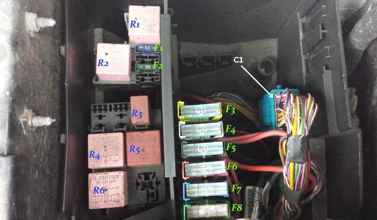
THE FUSEBOX PHOTO IS OF A TYPE 2 - THERE ARE 3 TYPES OF FUSEBOX FOR THESE VANS
Firstly under the passenger floor mat, disconnect the battery positive for over 15 minutes to reset all the systems and leave disconnected before trying any further investigation.
The most common cause, is corrosion in the blue connector plug on the right hand side in the Engine bay fuse box. Pulling the plug apart, spraying both sides with contact cleaner then pushing together a few times can fix the issue for a while. The pins are very small and very delicate so cleaning with contact cleaner and a toothbrush can remove a bit of the corrosion, gently rubbing with a fine nail board & contact cleaner can remove further corrosion on the pin side but the socket side is much harder to clean.
If this doesn't work, the next thing to do is clean the contacts on ALL the Relays & fuses, on the diagram, Relay R6 is for the engine control unit & FUSE F7 is for the ECU and engine management so these are the important ones. Being in the same environment as the blue plug, these also get corrosion on them, the fuses are a 60A MAXI FUSE, you can just replace them for new, under £4 for 10 on eBay if its easier and again use contact cleaner, to clean the fuse holders.
If you have tried all the simple fixes then its getting into more serious work but still easy to do with basic tools, you now need to test the cables from the plug to the ECU and the blue plug to the BCM, due to the thickness of the cables these can break inside very easily and many people have found broken wires to be the cause.
Firstly you will need a multimeter that works on ohms or this symbol Ω on the front, when you touch the 2 probes together the screen should read 1.0 showing zero resistance in the circuit. Now where it is marked on the photo C1, the 2 cables there are the canbus which are white with red stripe & purple, you will notice these are the only cables twisted together in the whole loom, majority of the time it is just these that fail but others have been reported broken and caused the same result with the immobiliser.
To start, you need to test the continuity of the blue plug so put the meter probes in the matching cables for the canbus both sides to test its definitely not the blue plug causing the issue. If it has a reading near 0 which is NO continuity then its back to cleaning the plug again or cut and rejoin the cables to bypass the plug.
If you are cutting cables, always solder them together, then use heat shrink tube to protect or use small heat shrink glue crimps that hold the cable together as the glue inside locks the crimp onto the cable. Check the 2 important ones first then check the other 46 wires to make sure they are all fine.
After testing the plug and its still not working we are into testing wires now.
REMEMBER TO ALWAYS LEAVE THE BATTERY DISCONNECTED WHEN REMOVING CABLES AND PLUGS ON THE BCM OR ECU
The BCM is under the steering wheel inside the dashboard plastics, need to remove the screw under the plastic trim by the wheel, pull both halves out and you will see the black box of the BCM in the gap, the bottom part is plastic welded in place, so need to pull the dial trim out as its just clipped in then break the plastic where its glued on at the right side of the under tray to give you some room. Now unclip the BCM so its free and you will see its security locked in place, drill the rivet out on the side of the metal band that goes around it and that will release the metal clamp that locks the important plug we need and you can then remove the BCM easily. Now you will see the other end of the top part of the blue plug cables, with the 2 twisted canbus cables, now using a long length of wire to link the blue plug to the multi meter in the cab of the van start testing continuity. With that length it may show some resistance but we want decent response to making the circuit, if you have nothing changing on your meter it's probably broken somewhere. If you have a good meter reading then its not this part of the loom but it is worth testing all cables for breaks.
Next up is testing the loom to the ECU, for some reason the manufacturers looped the cable from the blue plug all the way across to the engine block and back to the ECU hidden in the steel cage next to the fuse box. Many people have reported the loom rubbing on the bodywork under the fuse box and the cables wearing or breaking where the engine shakes on start up.
This is the trickier one to access as there are 2 security bolts with a special head locking the ECU away. The top one has a metal collar around it so drilling this out is the best way to remove it then the second one is on the left hand side towards the bottom which can easily be unwound with mole grips or pipe grips.
The rest of it is a selection of bolts to remove and another item to take off to remove the outer plate covering the ECU. Once removed you can undo the plugs and the top plug is the one with the twisted canbus cables that we need to check. Go through that ECU plug to the blue plug with the meter and test all cables with resistance.
If you find a faulty cable or cables they will need to be replaced.
Before reassembling, under the ECU is an earth cable, undo the bolt holding that in place and clean all corrosion from that cable crimp and the bolt. Next clean all the rust from the bolt and cage furthest back that the ECU is connected to the bodywork, as that is also an earth for the ECU and can cause issues.
Put it all back together and hopefully that has solved the issue somewhere along these instructions, if it hasn't it maybe a BCM failure which means you need to get matching Keys, BCM & ECU from the same used van or go to a dealer and have it changed and coded to the vehicle to match.
Hope this helped - I have included a list of what each
THE FUSEBOX PHOTO IS OF A TYPE 2 - THERE ARE 3 TYPES OF FUSEBOX FOR THESE VANS


